Optical Fibre: How Does Light Travel Thousands of Kilometres Down a Glass Thread?
Not long ago, our home broadband switched to fibre. A thin white cable comes in from outside and plugs into a small box, the “optical modem.” What carries information in that cable is not electric current but light: invisible infrared light whose strength changes billions of times a second, each change carrying information.
Doesn’t light travel in straight lines? How can it follow a cable round its bends? And if a thick block of glass is hard to see through, how can light travel thousands of kilometres inside glass?
Two common ideas
There are two common ideas:
- “The inside of a fibre is coated with metal, like a mirror.” No. The part that guides the light is all glass, with no metal mirror; outside it there is only a protective plastic coating.
- “Light is so fast it just zips through without fading.” Not true either. Light loses a little in every stretch of glass. Making it go further is a problem engineers have been working on for more than half a century.
What does an optical fibre look like?
Fibre glass is almost pure silicon dioxide, or silica; ordinary window glass also contains plenty of soda and lime. It isn’t melted from sand: silicon-bearing gases react at high temperature and “grow” a thick glass rod layer by layer, which is then drawn at about 2000 °C into a thread 125 µm across, slightly thicker than a hair. One rod can be drawn into more than a thousand kilometres of fibre.
A fibre has three layers:
- Core: at the very centre, only about 8 µm across. The glass has a trace of germanium, which makes its refractive index about 0.3% higher than the next layer’s.
- Cladding: around the core, 125 µm across, pure silica glass.
- Coating: two soft layers of plastic outside, about 250 µm across, protecting the glass.
The white cable at home is about 3 mm wide and 2 mm thick. Usually there is just one such fibre inside, with a thin steel wire or glass-fibre rod on each side to take the pull.
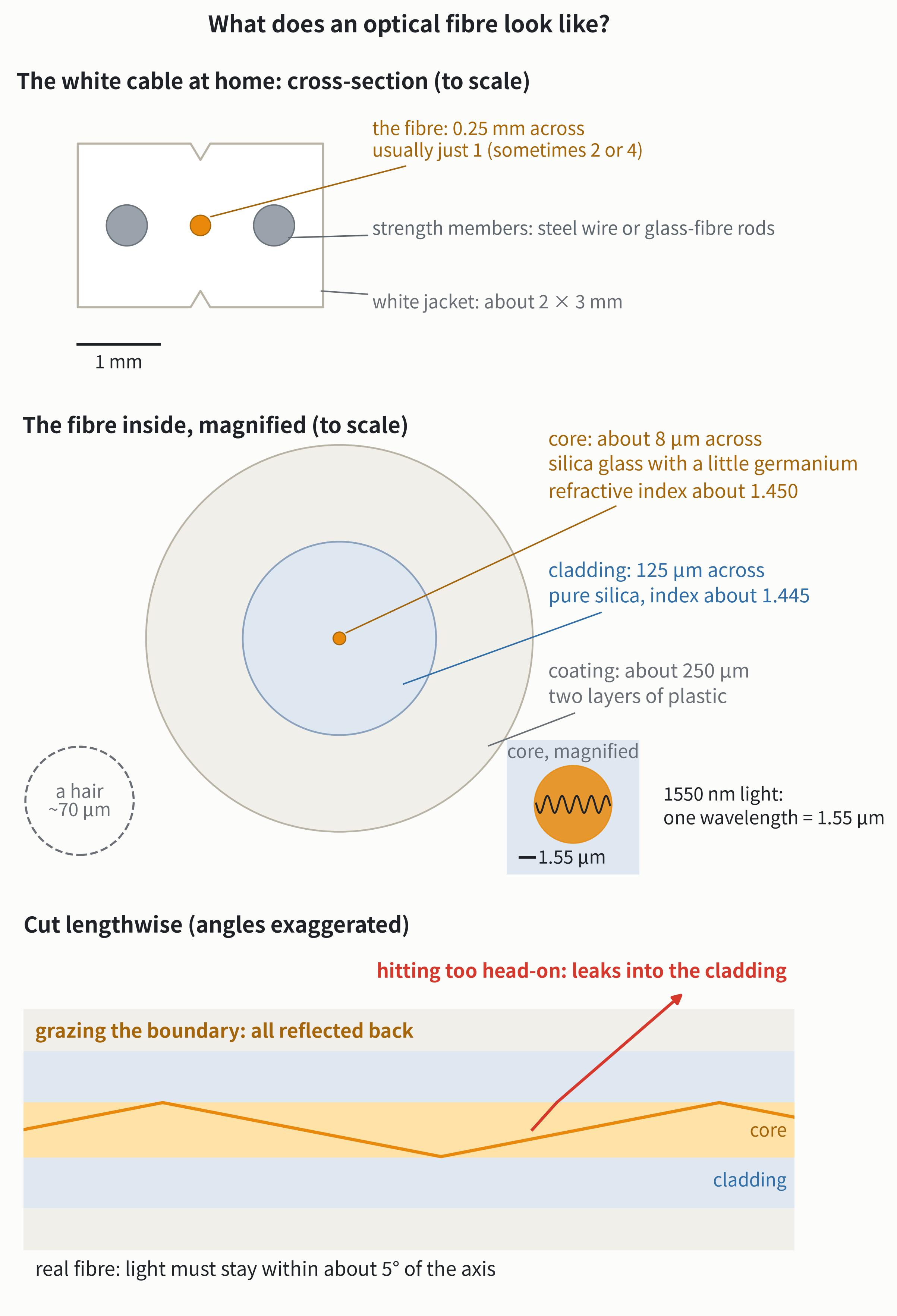
Fibre communication uses infrared light with wavelengths from 1260 to 1625 nm, while visible light spans roughly 380 to 750 nm. The core is only five or six wavelengths wide.
How does light follow a glass thread round a bend?
When light passes from a higher refractive index towards a lower one and almost grazes the boundary, none gets through: it is all reflected back. This is “total internal reflection.” Underwater in a swimming pool, look up at a slant: the distant surface looks like a silver mirror for the same reason.
In the core, light travels almost along the fibre. It grazes the boundary between core and cladding and bounces back; grazes again, bounces again. Wherever the fibre bends, the light follows. The core’s index is only 0.3% higher than the cladding’s, so the condition is strict: the light must stay within about 5° of the fibre’s axis to be reflected completely. At larger angles, that is, closer to hitting the boundary head-on, part of the light leaks into the cladding.
The first thing to bend light this way was water. In 1841 the Geneva physicist Daniel Colladon let water run from a hole in the side of a tank and shone a strong light in from behind. The light was trapped in the curving jet, and wherever the water landed, it lit up. The colourful “luminous fountains” at the 1889 Paris Exposition used the same trick.
How hard a bend makes it leak?
Bend a fibre too sharply and the boundary on the outside of the bend turns to face the light. The light hits it beyond that 5° limit and leaks out through the outside of the bend.
- Standard fibre (used for long distances and in neighbourhoods): keep the bend radius above about 3 cm.
- Bend-insensitive fibre for homes: a ring of even lower index, a “trench,” around the core holds the light more firmly. By the international standard, one turn around a 1 cm radius loses at most about 2% of the light; a 7.5 mm radius, at most about 11%.
So at home, don’t kink the fibre (no bend tighter than a small coin) and don’t let doors or furniture pinch it. Keep dust caps on unused connectors and don’t touch the end faces. The core is only 8 µm across: a fingerprint or a speck of dust can block most of the light.
A more accurate picture: a wave pattern in the core
The core is only five or six wavelengths wide, so light in it doesn’t really behave like a set of rays. It is more like a steady wave pattern, called a “mode.” A core this thin carries only one mode, so it is called “single-mode fibre.” All long-distance links use it: in a thicker core (say 50 µm), light can bounce along at many different angles, the slanting paths are longer and arrive later, and a pulse gets smeared out. This “multimode fibre” is used only over a few hundred metres.
The edge of this wave pattern also reaches a few micrometres into the cladding, so the cladding must be extremely pure glass too. The wave picture also explains bend loss more accurately:
- Light is a little slower in the core (higher index) and a little faster in the cladding (lower index). The pattern as a whole moves along the fibre at a speed in between.
- When the fibre bends, the whole pattern has to turn together, like a row of runners holding hands: the further from the centre of the bend, the faster they have to run.
- The part of the pattern reaching into the cladding on the outside reaches a point, some distance from the core, where the required speed is more than light can travel in the cladding glass. It can’t keep up, falls away from the pattern and leaks out. The tighter the bend, the closer that point is to the core, and the more leaks.
First, a unit: the decibel
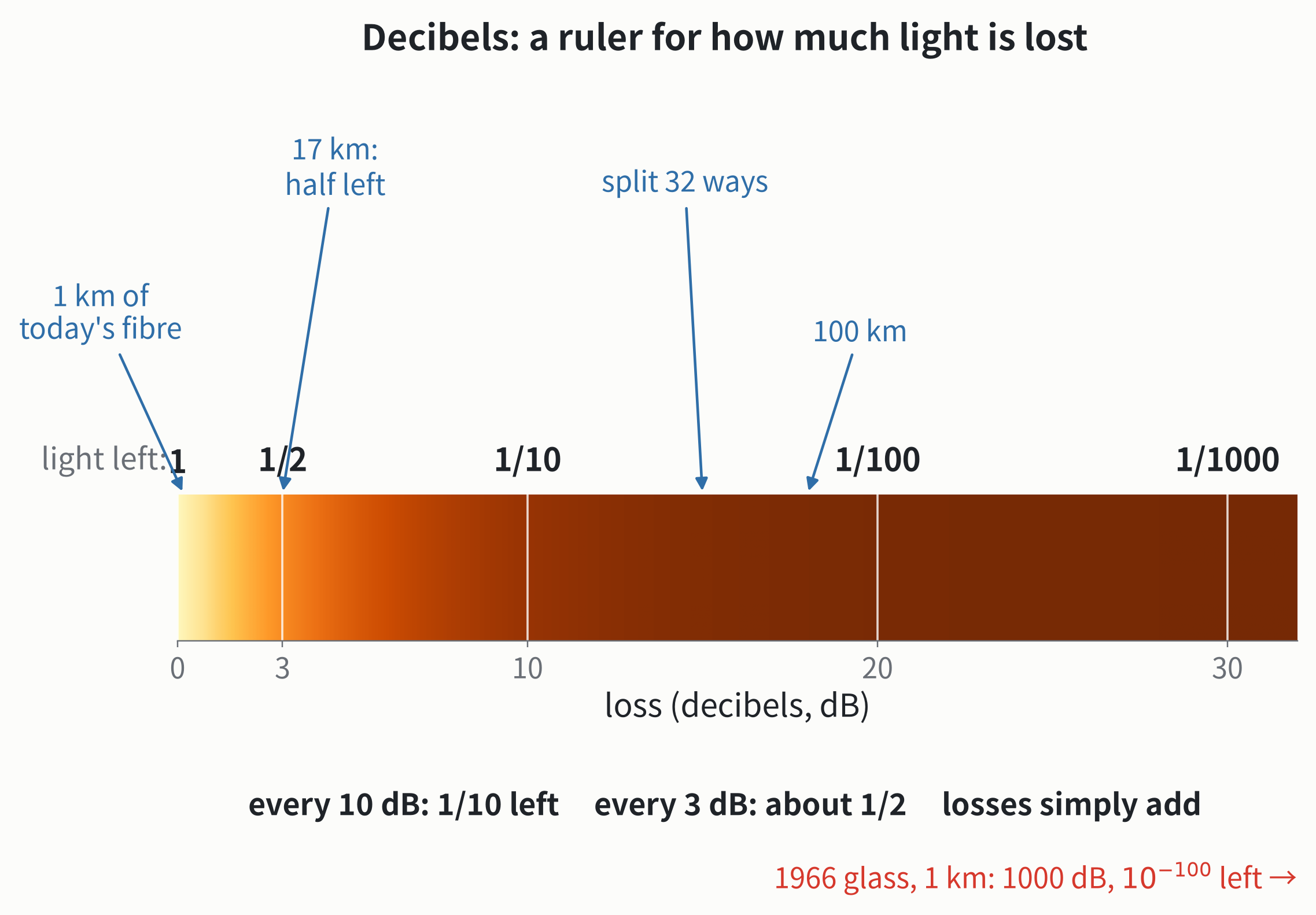
Light gets weaker as it travels along a fibre. To say how much weaker, engineers use the decibel (dB), a way of counting factors:
Turned around, the light out is of the light in:
| Loss | Light left |
|---|---|
| 0.18 dB (1 km of today’s fibre) | 96% |
| 3 dB | about 1/2 (because ) |
| 10 dB | 1/10 |
| 20 dB | 1/100 |
| 30 dB | 1/1000 |
| 1000 dB |
The handiest thing about decibels is that they simply add: lose 3 dB, then another 3 dB, and that’s 6 dB in all, 1/4 left. Today’s fibre loses 0.18 dB per km: 17 km is about 3 dB, half left; 100 km is about 18 dB, only 1.6% left.
So where does the light’s energy go?
Mainly to two places:
- It is scattered. Glass is molten silica that has cooled and set before its molecules could line up, so some spots are a little denser and some a little looser. These uneven patches are much smaller than the wavelength of light, and light that meets them is scattered a little in all directions. This is the same Rayleigh scattering as in Why Is the Sky Blue, and Why Are Sunsets Red?: its strength goes as one over the fourth power of the wavelength, so shorter wavelengths scatter much more.
- It is absorbed. Silicon and oxygen atoms are joined as if by tiny springs, which vibrate. Beyond about 1600 nm, the light’s frequency starts to approach these vibrations and is absorbed, turning into heat.
Older fibre had one more absorber. During manufacture, the silicon-bearing gases react in a hydrogen–oxygen flame, and a little hydrogen gets into the glass, bonding with oxygen into hydroxyl (the O–H in a water molecule). It absorbs light near 1383 nm, making a “water peak.” Engineers later learned to flush the hydroxyl out with chlorine gas while the glass is sintered; most fibre today has no noticeable water peak.
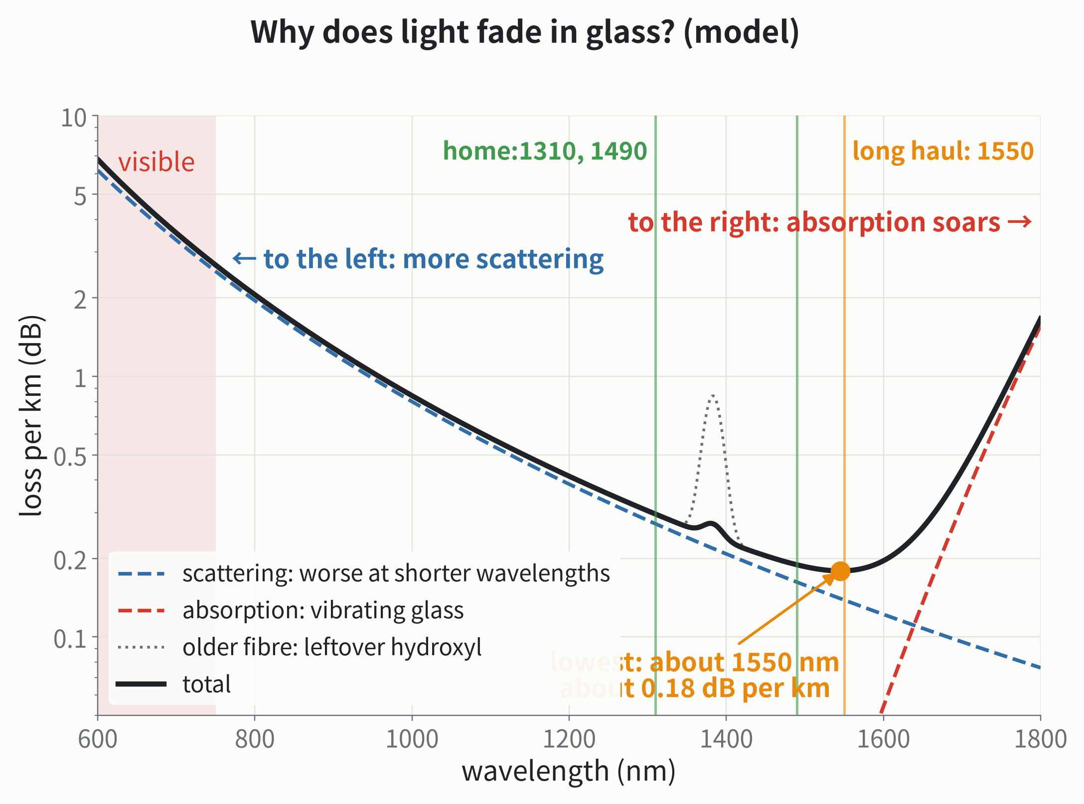
Read the figure from left to right. In the visible range, scattering alone costs several dB per km, which is why fibre doesn’t use visible light. Moving right, the wavelength grows and scattering falls fast: from 850 nm to 1550 nm the wavelength less than doubles, yet scattering drops to about one eleventh. Further right, past 1600 nm, absorption shoots up. One curve falls, the other rises, and the lowest total loss lands near 1550 nm. That is why long-distance fibre uses 1550 nm.
From “opaque” to losing only 4% per kilometre
In the 1960s, the best glass lost about 1000 dB per kilometre: by the table above, only of the light survived one kilometre. Many people concluded that communicating through fibre was a fantasy.
In 1966, Charles Kao, a Chinese-born engineer at a telecommunications laboratory in Britain, and his colleague George Hockham published a paper showing that glass was opaque not because of physics but because of impurities such as iron and copper. Purify it, and the loss could fall below 20 dB per km, good enough for communication. Look at a pane of window glass edge-on: it is green, and that is iron in the glass absorbing light.
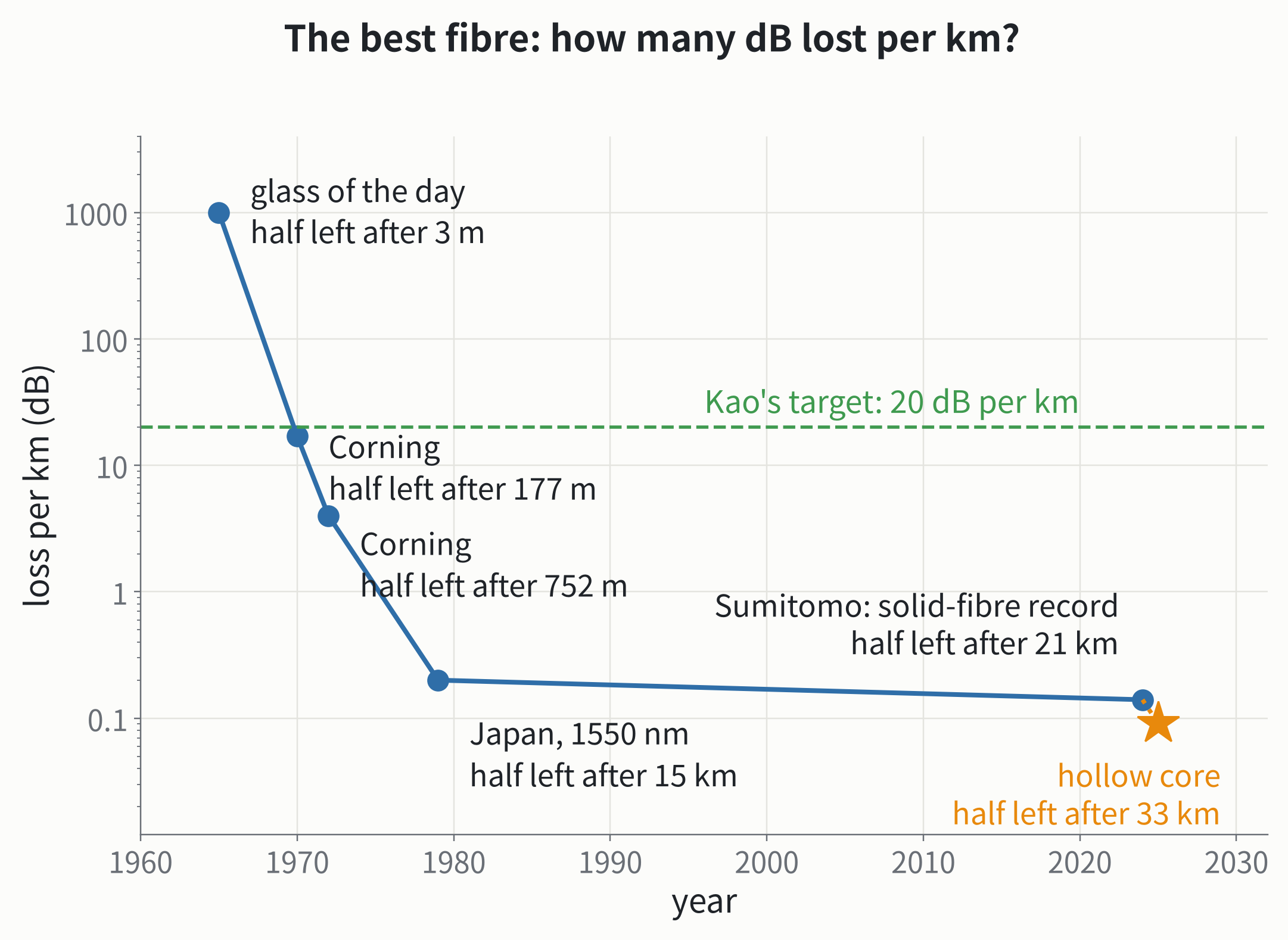
In 1970 Corning made fibre losing about 17 dB per km; in 1979 researchers in Japan reached 0.2 dB per km at 1550 nm. From left per kilometre to losing only 4.5% per kilometre took just over a decade. In the decades since, solid fibre has improved only from 0.2 to about 0.14, because Rayleigh scattering is a property of the glass itself, and no purification can remove it.
In 2009 Kao won the Nobel Prize in Physics. The other half of that year’s prize went to the two scientists who invented the CCD image sensor (see How Does a Phone Take a Photo?). Kao already had Alzheimer’s disease, and his wife delivered his Nobel lecture for him.
Light in air: hollow-core fibre
If glass itself scatters and absorbs light, why not keep the light out of the glass altogether? That is “hollow-core fibre”: air in the middle, surrounded by a few very thin glass tubes whose walls are only about 0.5 µm thick.
Air has a lower index than glass, so total internal reflection doesn’t work here. It uses a different trick: the wall thickness is chosen so that the waves reflected from the front and back surfaces of the thin glass add up, turning the light back to the centre, the same physics as thin films in Why Are Soap Bubbles Colorful?. Each tube also has two smaller tubes nested inside: light that gets past the first membrane is turned back by the second and third, and the more layers, the less escapes. Only about one part in 100,000 of the light touches glass.
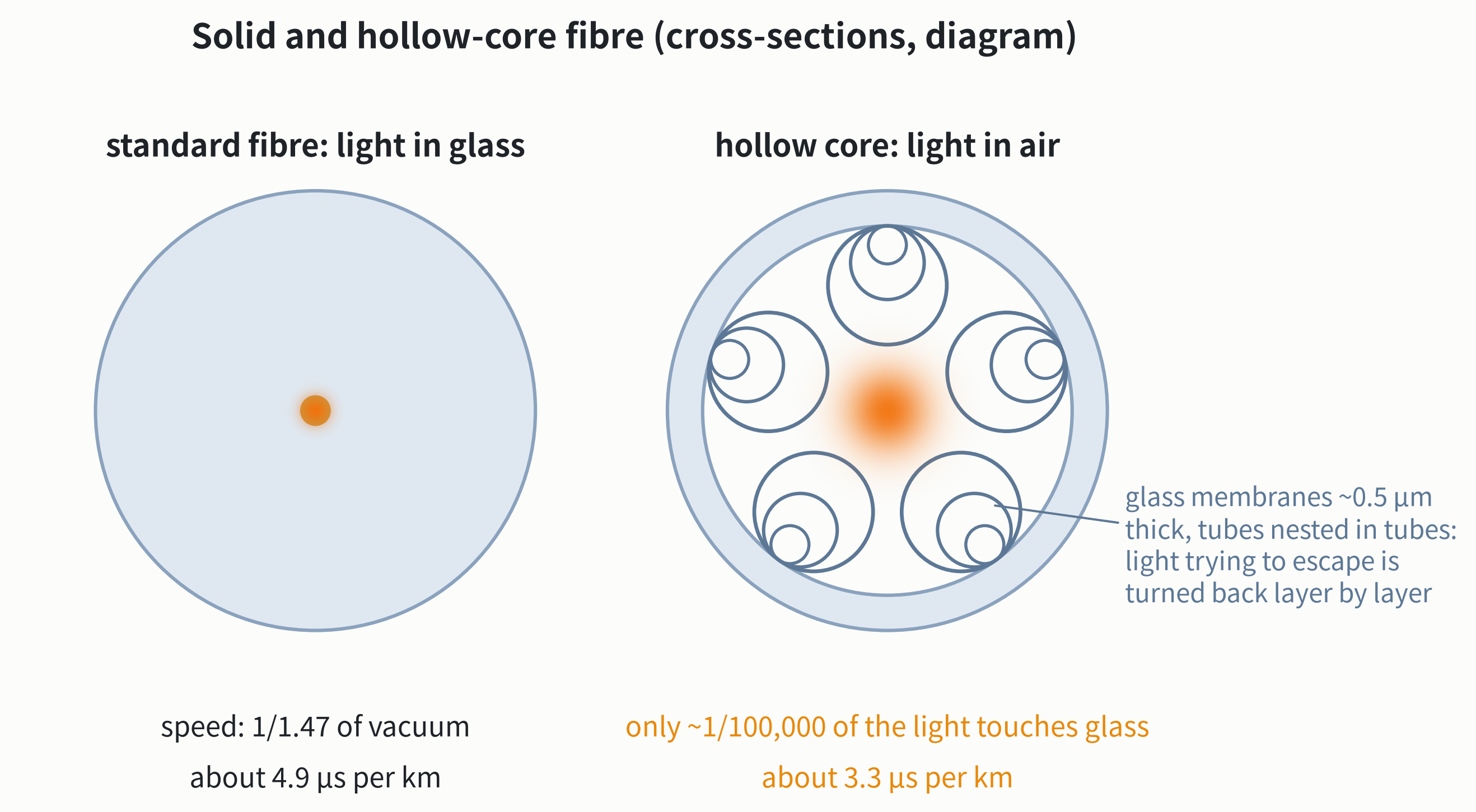
In September 2025, a team from the University of Southampton and Microsoft reported in Nature Photonics a hollow-core fibre losing only 0.091 dB per km, the first to beat the best solid fibre. That autumn, teams in China, including Jinan University and the fibre maker YOFC, reported about 0.05 dB per km at the European Conference on Optical Communication. Light in air is also faster, saving about 1.5 µs per km, precious for links between data centres and for time-critical financial trading. Microsoft reportedly already carries live traffic over about 1200 km of such fibre.
Hollow-core fibre has its difficulties, though. With the light held in only by thin membranes, it is more sensitive to bending than standard fibre: it generally needs a bend radius of several centimetres and can’t be kinked like a home fibre. Keeping dozens of sub-micrometre membranes the same shape along tens of kilometres is hard to manufacture; joining it to standard fibre is trickier; and it is still expensive.
Listening to the light’s echo
A small part of the scattered light travels back down the fibre. Engineers send a short pulse of light in at one end and “listen” to the echoes: the later an echo arrives, the further away it came from. Where the echo suddenly weakens there is a joint or a bend; where it stops, there is a break. The instrument is an optical time-domain reflectometer (OTDR), and it can locate a fault tens of kilometres away to within a few metres. The same idea turns a cable into a long “microphone”: scientists have used undersea cables to detect earthquakes.
Thousands of kilometres: amplify the light every few tens of kilometres
Even in the best fibre, after a hundred or two kilometres the light is too weak to read. The early solution was to turn the light into electricity every few tens of kilometres, amplify and clean it up in circuits, and turn it back into light. TAT-8, the first transatlantic fibre cable, opened in 1988, worked this way.
In 1987, the University of Southampton in Britain and Bell Labs in the United States, almost at the same time, made the erbium-doped fibre amplifier: add the rare-earth element erbium to a length of fibre and use another laser to “lift” the erbium atoms into a high-energy state. When signal light passes, one photon can “pull out” an identical one, one becomes two, two become four, and the light is amplified directly, without becoming electricity. This is the principle of the laser: stimulated emission.
Here is a lucky coincidence. Long-distance signals were already placed near 1550 nm, where the loss is lowest, so each span can be as long as possible and as few amplifiers as possible are needed; and erbium happens to amplify exactly 1530 to 1565 nm.
On land, amplifiers are usually every 80 to 100 km; undersea amplifiers are very hard to repair, so they are closer together, typically every 50 to 80 km, and a trans-Pacific cable holds more than a hundred of them. Amplifiers have a price: a lifted erbium atom sometimes drops back on its own and emits a random photon, which is also amplified and becomes noise, a little more at each amplifier. In the animation, after 960 km the signal is still about 450 times stronger than the noise; over ten thousand kilometres, engineers have to budget every span carefully.
Light pulses: the shorter, the wider the range of wavelengths
The simplest way to make light carry information is to switch it on and off: on for 1, off for 0. Each short flash of light is a “pulse.” At bits per second, each bit lasts only 100 picoseconds ( s), and in that time 1550 nm light oscillates about 19,000 times.
A pulse with a beginning and an end is not a single wavelength. A wave of one single wavelength would have to run from the infinite past to the infinite future; to make it start and stop, you have to add several waves of slightly different wavelengths. In the middle their crests line up and add up; away from the middle they fall out of step and cancel. The shorter the pulse, the sooner they must fall out of step, and so the more their wavelengths must differ.
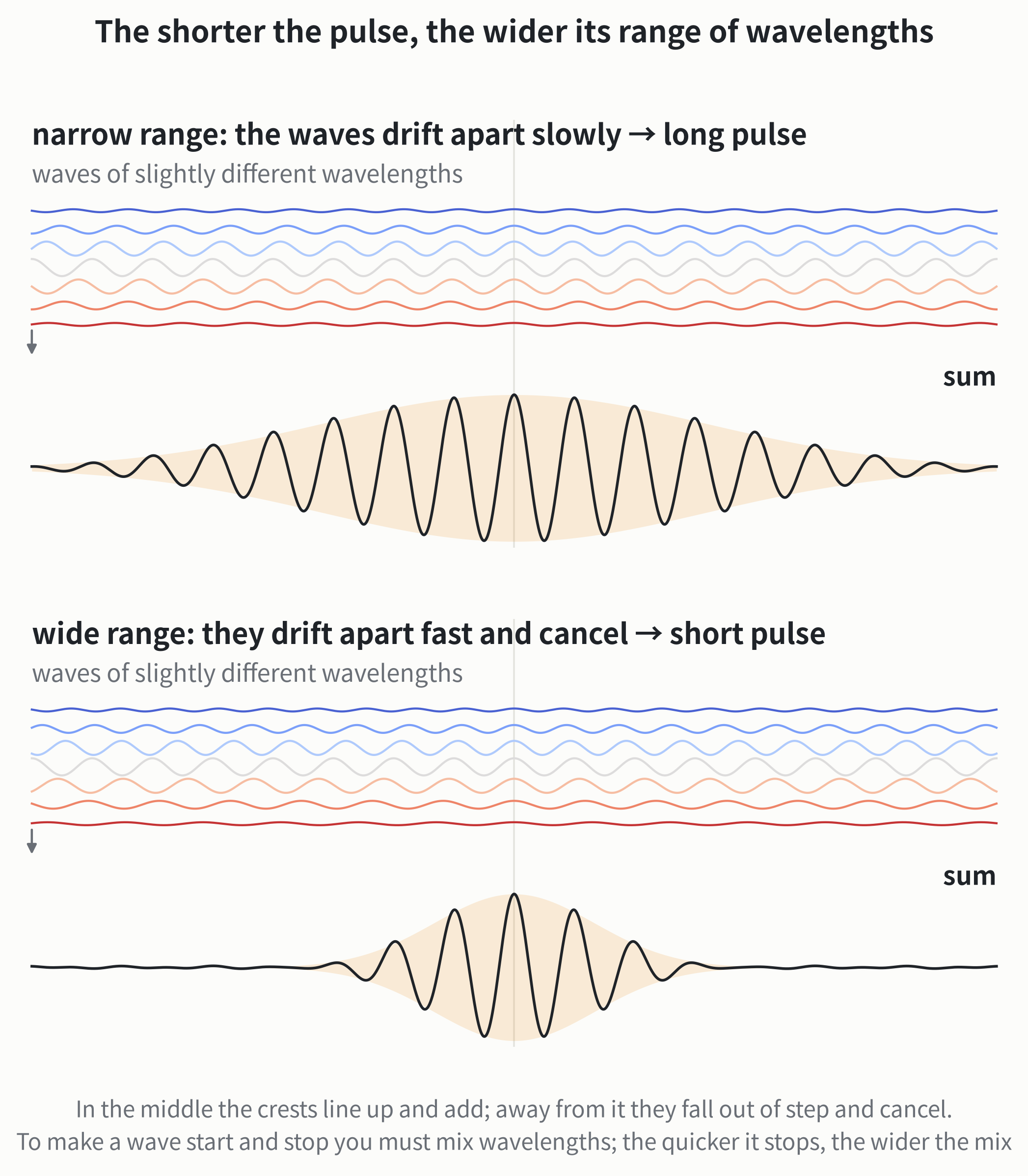
A pulse at bits per second spans about 0.1 nm of wavelength. That tiny range causes the next problem.
Another problem: pulses spread out
The refractive index of glass depends on wavelength, so different wavelengths travel at slightly different speeds. This is “dispersion,” the same effect that lets a prism split white light into a rainbow (see the prism and thin films in Why Are Soap Bubbles Colorful?). The slightly different wavelengths within that 0.1 nm drift apart as they travel, and the pulse is stretched.
At 1550 nm, wavelengths 1 nm apart arrive 17 ps apart after 1 km. A 0.1 nm range spreads by about 1.7 ps per km, so after about sixty kilometres it has spread by 100 ps, a whole bit, and neighbouring pulses run together. Near 1310 nm, standard fibre has almost zero dispersion, so shorter links often use 1310 nm.
The old fix was to splice in a reel of “dispersion-compensating fibre” every so often. Its dispersion has the opposite sign: the wavelengths that ran ahead in ordinary fibre run behind in it, and the two cancel. Today it is mostly done by computation: a chip at the receiver measures both the strength and the phase of the light wave, in effect recording the whole waveform, and undoes the dispersion step by step with mathematics.
One fibre, many “colours” at once
One wavelength can carry only so much data, so use many at once. Place a wavelength every 0.4 nm between 1530 and 1565 nm, and one fibre carries more than eighty signals at once without interfering; at the far end, a prism-like component separates them. This is wavelength-division multiplexing (WDM).
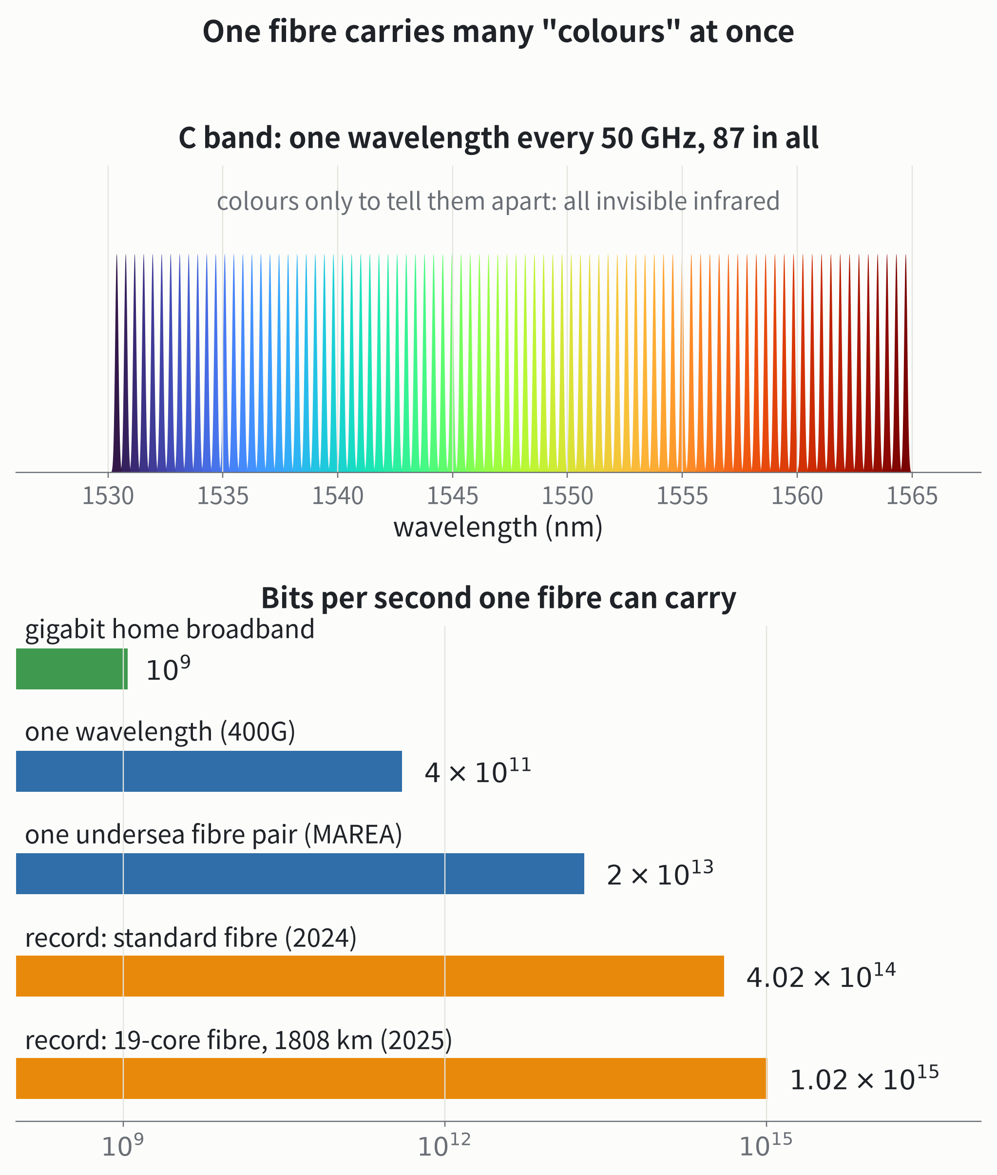
Each wavelength, as in How does radio carry sound and data to your phone?, varies both the strength and the phase of the wave, carrying several bits at a time. So one wavelength carries bits per second, and one undersea fibre pair (one each way) about , enough for twenty thousand gigabit homes downloading at full speed at once. In 2024, Japan’s National Institute of Information and Communications Technology (NICT) used all six low-loss bands to send bits per second through one ordinary commercial fibre; in 2025, NICT and Sumitomo Electric sent bits per second over 1808 km through a fibre as thin as a standard one but with 19 cores inside.
How does data find its way?
Light just runs; who picks the route? Data is cut into small packets, each labelled with its destination address (IP address). From your modem, packets go to the exchange and into the operator’s network, where every “router” along the way looks up a table and decides whom to hand them to next, like parcels passing through sorting centres. If a line breaks or gets congested, routers switch to another route. Light in glass takes about 4.9 µs per km, so a round trip costs about 1 ms per 100 km: the more detours, the slower the network feels.
Cables on the seabed
Most internet traffic between continents goes not by satellite but through undersea cables. The cables in service total about 1.4 million km, more than thirty times around the equator. In the deep ocean, a cable is only about as thick as a garden hose: a few fibre pairs in the middle, wrapped in steel wires, a copper tube that carries power to the amplifiers (fed from the landing stations at over ten thousand volts), and a plastic sheath. In shallow water near the coast, extra layers of thick steel wire are added against fishing gear and anchors.
They are fragile too. In February 2024, in the Red Sea, a cargo ship that had been attacked and abandoned drifted, probably dragging its anchor, and cut three cables; in September 2025, several more Red Sea cables broke near Jeddah in Saudi Arabia, and traffic between Asia, the Middle East and Europe slowed noticeably as it was rerouted. Repairs need special ships to haul the broken ends up from thousands of metres down, and can take weeks or months.
The last stretch to your home
The final few kilometres use a very economical trick: light from the exchange travels down one fibre to your neighbourhood, where a “splitter” divides it into dozens of shares, one per home. The modem receives at 1490 nm and sends at 1310 nm, both directions sharing the same fibre.
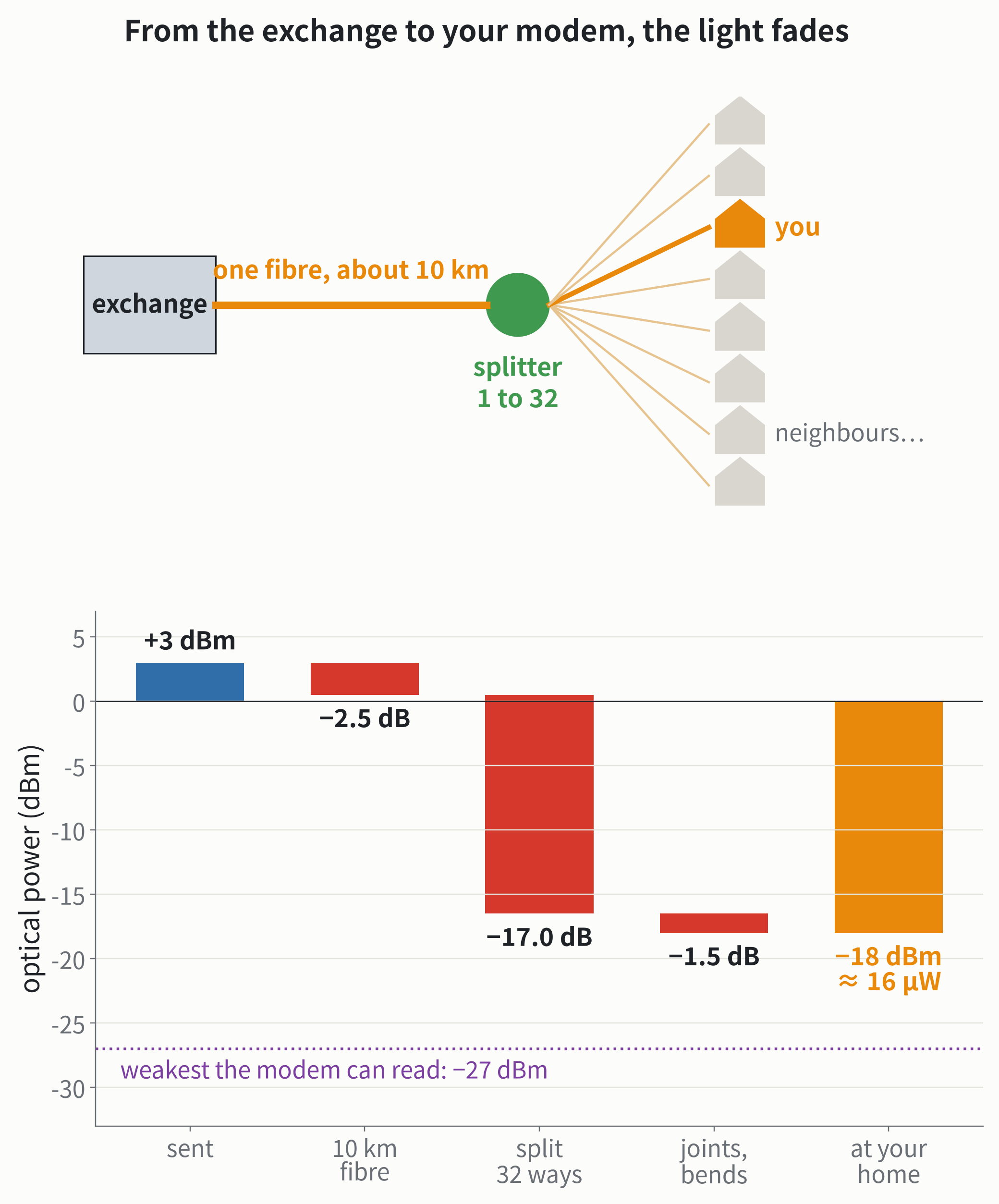
With decibels the budget is just addition: +3 − 2.5 − 17 − 1.5 = −18 dBm. Splitting 32 ways costs 17 dB in one step, far more than 10 km of fibre. The light reaching your home is only about 16 µW, more than 60 times weaker than a 1 mW laser pointer, and that is plenty: each bit arrives as about 50,000 photons. Many modems show “received optical power” on their admin page, usually between −8 and −27 dBm; if the modem’s “LOS” light turns red, no light is arriving.
This light is invisible to the eye, and a phone camera can’t see it either. A phone camera’s chip is made of silicon, and a photon needs at least 1.12 electronvolts to free an electron in silicon (see How Does a Phone Take a Photo?); photons at 1310 and 1490 nm carry only 0.95 and 0.83 eV. So the detector in the modem that turns light into an electrical signal can’t be made of silicon. It is made of indium gallium arsenide (InGaAs), a semiconductor whose threshold is only about 0.75 eV.
In a sentence: a fibre’s core is silica glass with a trace of germanium, its index about 0.3% higher than the cladding’s; light grazing the boundary is reflected completely, so it follows the glass thread round bends, but a bend that is too sharp makes it leak. At short wavelengths, scattering from the glass’s uneven density is strong; at long wavelengths, absorption by vibrating molecules is strong; 1550 nm sits in the valley between them, losing only about 0.18 dB per km, half the light still left after 17 km. Add erbium-doped fibre to amplify the light directly every few tens of kilometres, chips to compute the dispersion away, and dozens of wavelengths in one fibre, and light can carry data across oceans.
Try it yourself
- Light in a water jet: poke a small hole low in the side of a plastic bottle, fill it with water, turn off the lights, and shine a laser pointer through the bottle at the hole from the other side. The light is trapped in the jet, curves down with it, and lights a spot where the water lands.
- The green edge of a window: look at a pane of glass edge-on. It is green: those are the impurities Kao was talking about, iron in the glass absorbing light.
- A mirror in the pool: underwater, look up at a slant: the distant surface looks like a silver mirror. That is total internal reflection.
What we don’t know yet
How much more can a fibre carry? The more light is packed into a fibre, the more the light itself changes the glass’s refractive index, and different wavelengths start to interfere with one another. This “nonlinearity” sets a ceiling on capacity, and the best systems are already close to it. The way forward might be multicore fibre, hollow-core fibre, or using more wavelength bands; which is most economical is still open. Whether hollow-core fibre can become as cheap and durable as standard fibre and be laid across the oceans will take a few more years to tell.
Going further: numbers, formulas and sources
Total internal reflection. Light going from index to () is totally reflected when the angle of incidence (from the normal) exceeds the critical angle , . With and , : light must stay within about 4.8° of the fibre axis. Numerical aperture . Figure 2 exaggerates the contrast to , ; it is a 2-D ray trace, with leakage from the Fresnel equations.
Sizes. G.652 single-mode fibre: cladding µm, coating about 242 µm, core about 8 to 9 µm. A human hair is about 50 to 100 µm, varying from person to person. A home “bow-tie” drop cable is about 2.0 × 3.0 mm, usually with one fibre.
Bend loss. G.652 standard single-mode fibre: minimum design bend radius about 30 mm. G.657.A2 bend-insensitive fibre: 10 turns at 15 mm, 1 turn at 10 mm and 1 turn at 7.5 mm radius add at most 0.03, 0.1 and 0.5 dB at 1550 nm (about 0.7%, 2%, 11%). In the wave picture, the mode’s effective index lies between and ; at bend radius , beyond a distance from the axis on the outside, the mode would need a phase velocity above the cladding’s , and the field there becomes an outgoing radiating wave. With to 0.003, that distance is only ten to twenty micrometres at cm.
Single-mode condition. Only one mode exists when ( = core radius). Standard single-mode fibre is single-mode above 1260 nm; at 1550 nm the mode field diameter is about 10 µm, a little larger than the core.
Decibels. Fibre with loss (dB per km) leaves after km. dBm is relative to 1 mW: .
Loss model. Figure 4: Rayleigh scattering ( in µm, result in dB per km), infrared absorption , ultraviolet absorption , plus the hydroxyl peak at 1383 nm and 0.015 dB per km of other losses. It matches real fibre specifications (about 0.3 dB per km at 1310 nm, 0.18 at 1550 nm). The 1383 nm peak is the second overtone of the hydroxyl stretching vibration (about 2.7 µm).
Hollow core. In an antiresonant hollow-core fibre with glass membranes of thickness , light leaks at “resonances” near , with low-loss windows between them; for µm the widest window covers 1550 nm. Figure 6 shows a double-nested design (DNANF): five tubes, each with two more nested inside. Typical nested hollow-core fibres add little loss at bend radii above about 3 to 5 cm; standard single-mode fibre is about 1.5 cm.
Amplifier noise. Each erbium amplifier makes up the loss of an 80 km span (16 dB at 0.2 dB per km including joints), with a noise figure of 5 dB, adding noise of about dBm in a 0.1 nm bandwidth. With 0 dBm per channel, after 11 amplifiers the optical signal-to-noise ratio is about dB, about 450 times, consistent with the engineering rule of thumb dB.
A pulse’s range of wavelengths. Pulse duration and spectral width satisfy (Gaussian, full widths at half maximum). The pulses of Figure 9 have ps (intensity FWHM about 42 ps); the power spectrum’s FWHM is about 10.6 GHz, or nm. Figure 8 adds seven cosines with Gaussian weights, as an illustration.
Dispersion. Standard single-mode fibre at 1550 nm has ps/(nm·km), i.e. ps²/km. Figure 9 multiplies the spectrum by ; colour is the instantaneous frequency. The characteristic spreading length is km; after 100 km the pulses are about 3.6 times wider.
How fast. The group velocity in glass is about 1/1.47 of the vacuum speed, about 4.9 µs per km; in air about 3.3 µs per km.
To your home. Figure 11 uses common GPON: downstream at 1490 nm, about bits per second shared by the dozens of homes on one splitter; modem sensitivity about −27 dBm. An ideal 32-way split costs dB, about 17 dB in practice. −18 dBm at 1490 nm is about photons per second, about 48,000 per bit. InGaAs () has a band gap of about 0.75 eV and detects out to about 1700 nm.
Sources. Colladon: Comptes Rendus 15, 800 (1842). Kao and Hockham: Proc. IEE 113, 1151 (1966). Corning in 1970: IEEE Spectrum, “How Charles Kao Beat Bell Labs to the Fiber-Optic Revolution.” 0.2 dB per km: Miya et al., Electronics Letters 15, 106 (1979). Solid-fibre record 0.1397 dB per km (at 1566 nm; 0.1406 at 1550 nm): Sato et al., OFC 2024, Tu2E.1. Hollow core at 0.091 dB per km: Petrovich et al., Nature Photonics 19, 1203 (2025); about 0.05 dB per km: two ECOC 2025 reports (Jinan University et al., 40 km; YOFC et al., support-tube hollow-core fibre). Light in glass about , nested designs and bending: Poletti, Optics Express 22, 23807 (2014). Bend loss: ITU-T G.652, G.657. Erbium-doped fibre amplifier: Mears et al., Electronics Letters (1987); Desurvire et al. (1987). Capacity records: NICT press releases of 26 June 2024 and 29 May 2025 (the latter with Sumitomo Electric). Total cable length: TeleGeography. MAREA cable (8 fibre pairs, bits per second in all): Microsoft and Meta announcements, 2016. Red Sea cable cuts, September 2025: Microsoft Azure status page and NetBlocks reports.